
Line Current Measurement
Current measurement in Cathodic Protection system is critical to assess the overall system performance. The measurement techniques pose a great challenge to engineers in practice due to the low impedance of steel pipeline under the measurement. For example, resistivity of DN 700, 8mm WT steel line pipe is 10-5 Ωm. The internal resistance of a low-resistance shunt would be in the range of 1 and 10 mΩ. This would be on the same scale as the resistance of the circuit to be measured. Therefore, CP currents in particular section of pipeline are therefore determined indirectly by Ohm’s law by measuring voltage drop over a shunt. A few kilometres of cable need to be laid down for accurate and reliable measurement.
- Two Wires Span Method
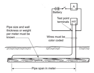
2-Wire Span Method for CP Current Measurement
4-Wire Span Method for CP Current Measurement
As long as OD and WT (or specific weight) of line pipe and distance between two wires are known, the current in pipeline section can be determined by measure the millivolt drop between the two wires.
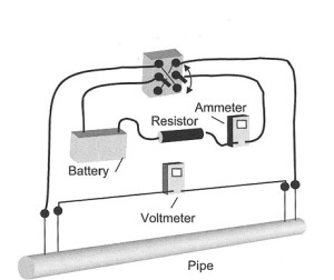
- Four Wires Span Method
Four-wire span method is to compensate the unknown line pipe resistivity due to fittings, non-uniform line pipe size, valves etc. different to the two-wire span method, each span can be calibrated separately, which give more accurate measurement.
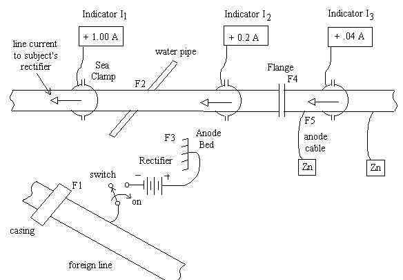
- Clamp measurement
Swain clamp, which is type of Hall Effect current measurement device, can be utilised for this purpose.
Error Sources
Swain clamp-on meter line curernt measurement
- Instrument error
Sensitive amplifier voltmeters are required since voltage drops in measurements of pipeline current are on the order of 1 mV. Recording potentiometers used for corrosion protection measurements have a range of 0 to 1 mV. These have an internal resistance in the balanced state of a few MΩ, and in the unbalanced state a few kΩ.
- Induced voltage
The measuring leads that pass over a street must be close together or twisted to avoid current impulses induced by the magnetic fields of vehicles.
- Thermal resistance
Voltage drops on the order of 0.1 mV can be caused by thermal voltages that can arise from the sun’s radiation on different metals, e.g., between pipeline and measuring rods.
- Contact resistance
Contact resistance is the one major practical issue in CP current measurement. Clean, low-resistance contact is always a challenge in field measurement. A permanent installation such as cadwelded or pin brazing electrical connection is preferred. However, they are not always available. Good contact can be achieved by metal rods and clamps if exposed metal fittings and line pipe can be utilised. Magnetic connection is always a practical way to achieve such temporary electrical contact.
Reference
- von Baeckmann et al, Handbook of Cathodic Corrosion Protection– Theory and Practice of Electrochemical Protection Process, Gulf Professional Publishing, 1997
Alireza Bahadori, Cathodic Corrosion Protection Systems-A Guide for Oil and Gas Industries, Elsevier, 2014
http://swainmeter.com, Line Current Monitoring
Holtsbaum, W. Brian. Cathodic Protection Survey Procedures, NACE International, 2009
Related Posts
 Electrical Short Pipeline Potential Measurement and its Implication in Pipeline CP Management Practice
- Cathodic Protection Numeric Method Summary Report
- Cathodic Protection Numeric Simulation
- Cathodic Protection Data Visualisation
- Off-Potential Interference by Solid State Decoupler
- DC STRAY CURRENT ANALYSIS AND MITIGATION
Good article