
- Field assembled insulating flange shall be tested with 1500VDC applied across the flange for 1 minute without causing break down or flash over.
- Electrical test to verify the insulating of the joint/ flange assembly for minimum of 1 MΩ for new flange.
- Electrical insulation of in service insulating joints can be measured by Swain Clamp On Ammeter.
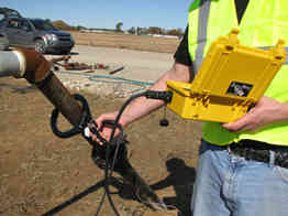
Swain meter to measure pipe current (photo from William H Swain company website)
- Electrical insulation of in service insulating joints can be tested by remote reference potential methods, if the potential difference is greater than 10 mV, then the insulation is sound.
- Point to point voltage measurement: if the potential difference is greater than 10 mV, then the insulation is sound.
- Magnetic compass method may be utilised for shorting of the insulating joints.
- Radio Frequency (RF) tester shall give reliable dielectric testing results, e.g. Tinker & Rasor RF-IT Note: proper types to be used.
- No Ohm meter method should be accepted as dielectric testing for insulating flange joint in service.
- High voltage insulation tester such as Megger tester shall NOT be used for in service environment.
- Welding should be carried out with the short connection of insulating joints, the jumper cable should be removed as long as welding is completed.
Related Posts
 Electrical Short Pipeline Potential Measurement and its Implication in Pipeline CP Management Practice
- Corrosion of Embedded Ferrous Metals in Woods
- Adenosine Testing and its Interpretation in Oil and Gas Field Microbial Status
- Cathodic Protection Numeric Method Summary Report
- Hydrotest Water Specification and Integrity Considerations
- Cathodic Protection Numeric Simulation
Pingback: Cathodic Protection Current Measurement - Corrosion and Corrosion Control
Such a great blog because this blog contains a lot of information which is amazing.