
Introduction
DC stray current is defined as current flowing through the path other than the intended. The DC stray current could be either natural sources, e.g. telluric, metallic mineral deposit, or artificial sources, e.g. foreign pipeline, HVDC transmission line, DC tram, etc. DC stray current is a big threat in pipeline integrity. The severity of the risk is a related to the soil resistivity: the lower the soil resistivity, the more likely to form such electrical conductance path, i.e. stray current related corrosion. The root cause of sewer explosion in 1992 Guadalajara Mexico is stray current corrosion of ductile iron pipe.
DC Stray Current Detection
Asset owner and corrosion engineer need to be vigilant to the sources of DC stray current including other pipeline cathodic protection units, HVDC transmission lines, DC railway and trams, solar farms, smelting plants, electroextraction plants etc. corrosion engineer should also be aware of latent sources such as telluric effect, strong magnetic deposit. Once suspected source of DC stray current is identified, further detailed monitoring should be planned to identify the magnitude of interference, assess the risk level to pipeline integrity and mitigation requirements.
- Pipe-to-Soil change along the pipeline caused by an interference source
- Change of line current magnitude and direction by an interference source
- Localised corrosion near an interference source
- Localised coating damage in the vicinity of an interference source
DC Stray Current Measurement
Using close interval potential survey (CIPS) to determine stray current pickup and discharge region
The principal anodic areas along the pipeline should be located. Sufficient cathodic protection current should be applied to cause a net protective current from the electrolyte to the pipe surface. The structure-to-electrolyte potential measurements by using close interval potential survey (CIPS) technique are performed on piping that is not cathodically protected. The structure-to-electrolyte potential survey, when used as a tool for locating probable anodic conditions on unprotected pipe, should be conducted by making individual readings at 3 m (10 ft) intervals along the route of the pipe. Probable anodic conditions are indicated at survey points where the most negative readings are determined. It may be desirable to confirm these suspected anodic conditions by making the two-reference-electrode test lateral to the pipe as described for the two reference-electrode method described below.
Direct Current Voltage Gradient method for current flow
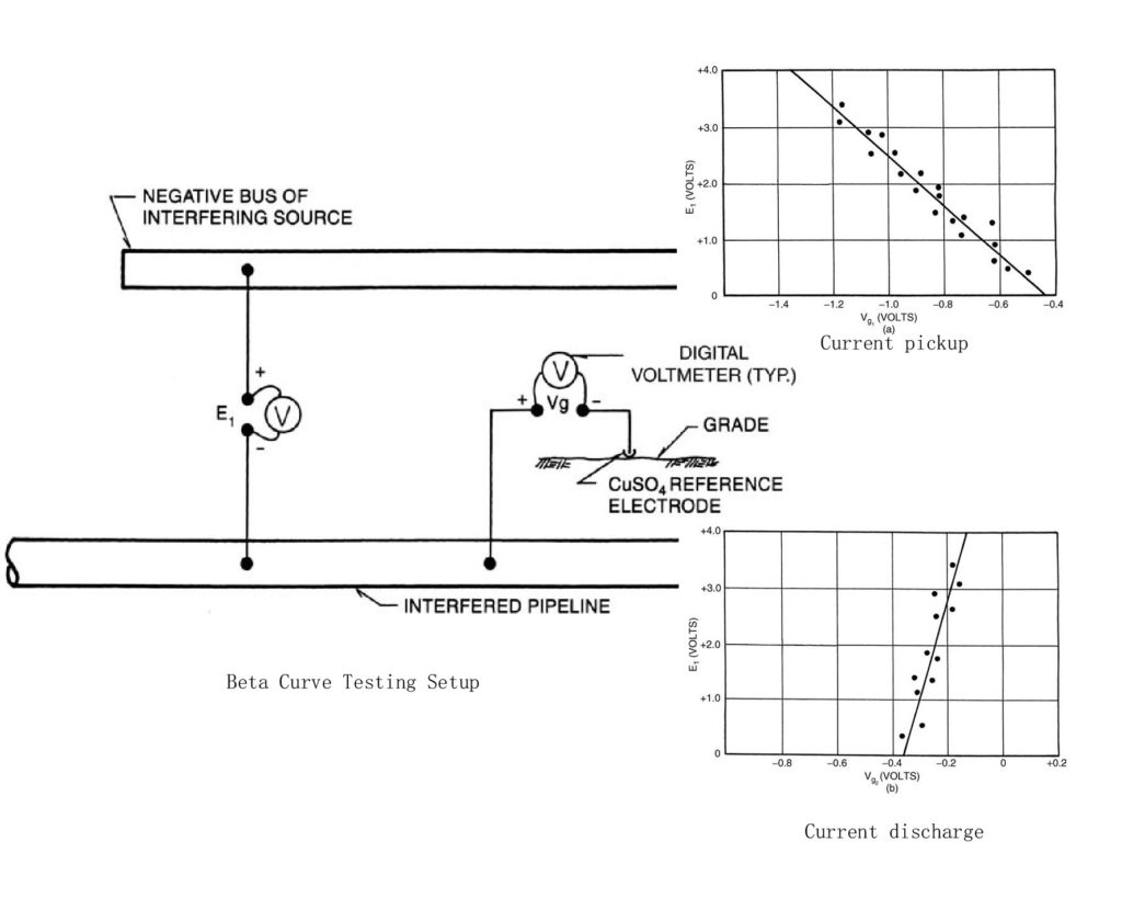
Beta Curve to determine stray current pickup and discharge
The direct current voltage gradient (DCVG) method, i.e., two-reference-electrode potential survey measures the direction of the potential gradient along the earth’s surface. Measurements should be made at 3 m (10 ft) intervals directly over the centerline of the pipe. This method is used to detect the probable current discharge (anodic) areas along a pipeline as well. However, this method is more appropriate to poor coated and/or bare pipeline. For well coated pipeline, the voltage gradient is not used as a standalone method for identifying stray current pick up and discharge. Suspected anodic conditions and their magnitudes can be confirmed by making two-reference-electrode tests laterally to the pipeline. One reference electrode is placed over the line and the other spaced laterally the same distance as for the transverse measurements over the line. These tests should be made on both sides of the pipe to verify that current is leaving the line.
Line Current Direction and Magnitude Measurement
It is important to use line current flowing direction to determine source and extent of stray current pickup and discharge section. This may be performed by Swain Clamp, two wire span method, four wire span method outlined in line current measurement.
DC Interference Mitigation
- Auxiliary CP, either impressed current or sacrificial anode, is utilised to compensate the too positive potential around current discharge region
- An interference cell, normally a bank of sacrificial anodes, is installed as a stray current discharging point;
- Sacrificial anodes are installed on both interfering and interfered structures to allow safe discharging of stray current between two.
- Relocating interfering anodes
- Shielding and/or recoating current pickup section to limit the stray current magnitude;
- Design and install electrical resistance bond to allow the return of stray current safely.
Mitigation Effectiveness
CIPS after the mitigation
CIPS to confirm the pipe-to-soil potential in current discharge section to acceptable level
Line Current Measurement after the mitigation
Line current measurement to confirm no current discharging
Beta curve confirmation for the slope of maximum of exposure section
Develop the beta curve to identify the most severely affected sections. This is most valuable for the dynamic interference sources, e.g. telluric, DC tram and railway etc. If the CP unit is operated under auto potential mode, its anode bed may also be taken as dynamic interfering source.
Reference
R. Winston Revie; Uhlig’s corrosion handbook; 2011 by Wiley
TM0497-2012, Measurement Techniques Related to Criteria for Cathodic Protection on Underground or Submerged Metallic Piping Systems, NACE
SP0207-2007, Performing Close-Interval Potential Surveys and DC Surface Potential Gradient Surveys on Buried or Submerged Metallic Pipelines, NACE
SP0169-2013, Control of External Corrosion on Underground or Submerged Metallic Piping Systems, NACE
Related Posts
 Internal lining testing methods against depressurisation: ISO 15741 vs NACE TM0184
- Electrical Short Pipeline Potential Measurement and its Implication in Pipeline CP Management Practice
- Metal Dusting: recent progress and industrial experience
- Cathodic Protection Numeric Method Summary Report
- Cathodic Protection Numeric Simulation
- Cathodic Protection Data Visualisation
Wow, that’s a really clever way of thikinng about it!
I’m not certain where you are getting your information, however
great topic. I needs to spend some time studying more or understanding more.
Thanks for magnificent info I used to be searching for this info for my mission.